Microcontroller vs Display
Connecting Displays to Microcontrollers is … fun. There’s quite a few different technologies to be aware of. Displays that use the same technology can have wildly different labeling. And the labeling on the pinout of the Microcontroller might also not be helpful in letting you know where to plug what into.
Look at these two 1.8 inch TFT LCD displays for example:
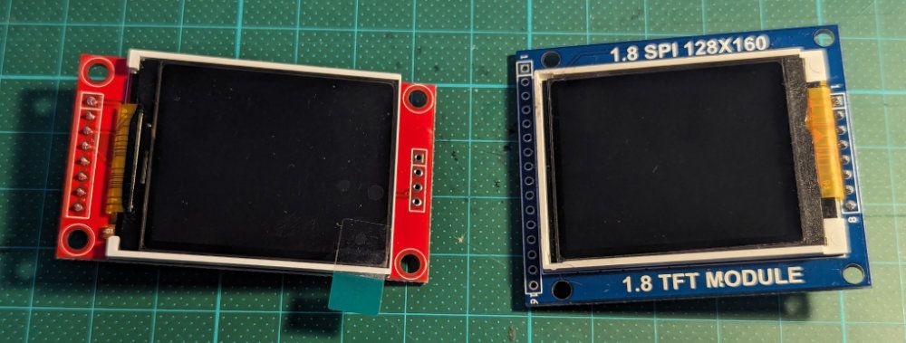
They
✅ look the same
✅ they both use SPI
✅ both run with a ST7735 driver
But look at their pinout! It’s almost completely different!! 🙀
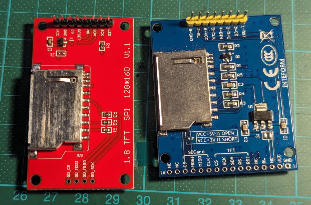
Red Display: LED, SCK, SDA, A0, Reset, CS, GND, VCC
Blue Display: RST, CS, D/C, DIN, CLK, VCC, BL, GND
Now look at the pinout of a recently released MicroController like the ESP32-S3 dev kit… Should the CLK pin on the display be connected to one of the many pins that have CLK in their name? Like FSPICLK maybe? It’s got “SPI” and “CLK” in it, no idea what the “F” means though. 🤷♂️ Well… good luck.
Order into Chaos
It might not look like it, but both displays actually have pretty much the same pins - just in different order and they use very different abbreviations for the same things. They both use SPI after all, but… what even is that?
Let’s look at the different protocols that microcontrollers can use to communicate with displays…
Communication Protocols
TL;DR: ➡️ use SPI. It has a few more wires than I2C, but is much faster! (So if you’re building your own mini handheld gaming console, that’s probably the way to go), I2C is totally fine for most things, UART is fine if you just want to display some text. Parallel is only needed in extreme performance cases and requires a whole lot of pins.
UART - Universal Asynchronous Receiver/Transmitter)
4 Pins, probably SLOW
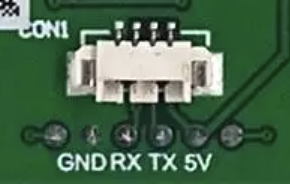
Not so much a protocol, but a circuit for asynchronous serial communication. It has one wire for transmitting (TX) and one wire for receiving (RX) with a configurable transmission speed.
The big downside of UART is that it’s really only made for one thing to talk to one other thing, so - unless your microcontroller has multiple sets of TX/RX pins - you can’t hook up multiple things via UART.
I2C (Inter-Integrated Circuit)
4 Pins, Okay for small displays
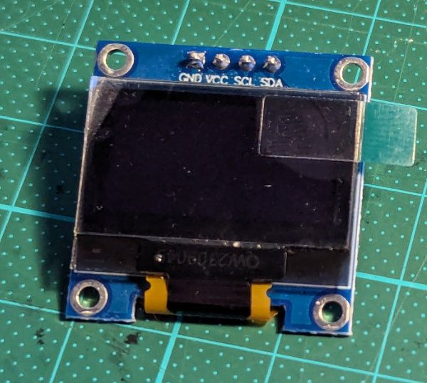
A synchronous multi-master, multi-slave serial communication bus. Allows for complex communication scenarios. Only has a single data line that is used for sending and receiving (it uses packets to make sure everything gets where its supposed to go), and a clock line to synchronize data transmission. Slower than SPI, but totally fine if you’re not doing anything too crazy
SPI - Serial Peripheral Interface
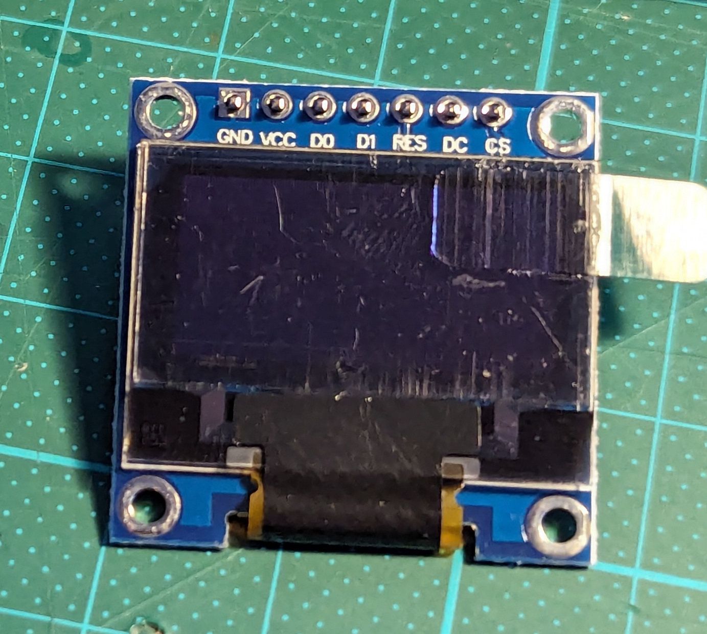
7 Pins, Best for small displays - Power, Ground, Backlight and four main lines: MISO (Master In Slave Out), MOSI (Master Out Slave In), SCK (Serial Clock) and SS (Slave Select).
SPI is a good way for a microcontroller to talk to multiple devices. The Controller (Master) device controls the communication and the Responder (Slave) responds.
SPI has good speed and efficiency (higher speeds than I2C). It doesn’t require a complex protocol and can transfer Data in a full-duplex manner (send and receive at the same time).
Most displays use a simplified version that doesn’t include a way for the display to talk back to the microcontroller. They basically only do MOSI (Master Out Slave In) and ignore MISO (Master In Slave Out) and instead use a Data/Command line that tells the display if it’s receiving pixel data or commands for the display controller.
Parallel
Many Pins, Super fast, but … did I mention so**** many** pins?**
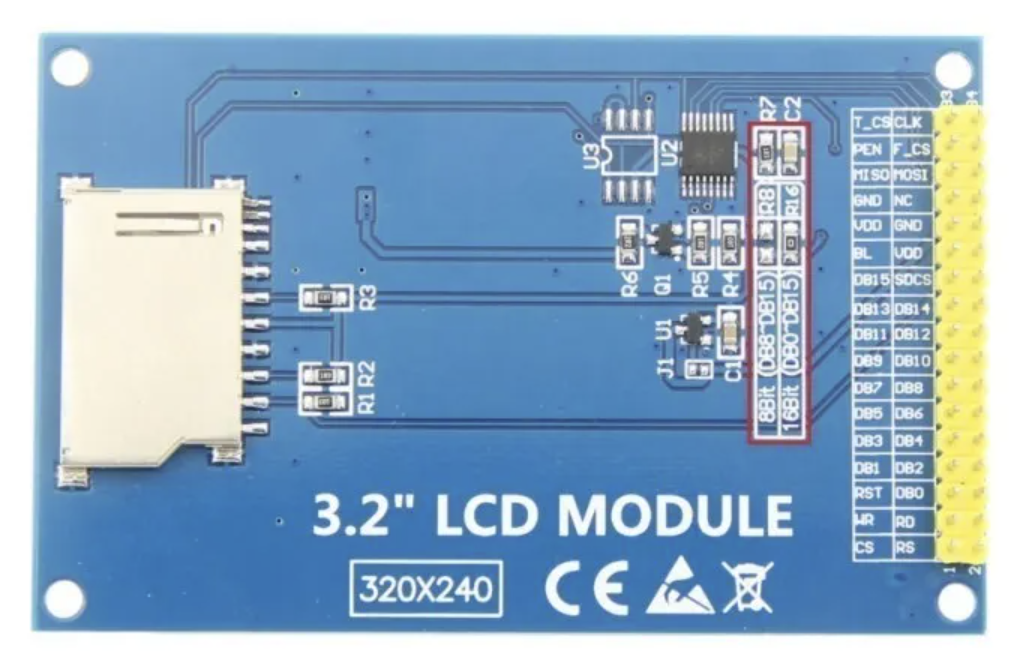
Multiple Data Lines! (With 8bit, meaning 8 lines, it can send a whole byte at once) Plus some extra connections for other stuff. Using Parallel might make sense for higher screen resolutions where you need to send a lot of data for each frame.
Haven’t tried this personally yet. Just know that this exists.
Hooking things up
Armed with this knowledge we can now begin to think about hooking things up. We’ll need to:
-
Connect all of this to relevant pins on our Microcontroller of choice
-
Find a display Library that supports our display and configure it
But which are the relevant pins and what library should we use?
Well, as far as I can tell, microcontrollers are so configurable that it doesn’t matter all too much which pins you use as long as you then configure your library correctly.
For example: This is how I hooked up the red 1.8” TFT LCD display to an ESP32-S3-DevKitC-1:
Take note of how I’m not using any of the ports that have SPI in their name, or CLK or anything like that. But you do want to stick to 3v3 and GND of course… 😉
The important part is to take note of the GPIO pins and configure your display library accordingly!
🎵 Intermission - Framebuffer 🎵
Can your microcontroller even handle a color display?
The biggest limitation for using framebuffers with microcontrollers is RAM. You usually want to keep an entire screen’s worth of buffer in RAM. If you work with 1-bit color (meaning every pixel could be represented by 1 bit - black or white), then a 128x64 pixel display would take 8192 bit = 1024 byte = 1KB to keep in RAM. The same size buffer with 16-bit (65.000 possible colors, every pixel represented by 16 bit = 2 bytes) would require 131,072 bit = 16,384 byte = 16.4KB.
An Arduino UNO has 2KB of RAM, so no chance of fitting that. An ESP32-C6 on the other hand has 520KB of RAM (not all usable, but still), so has no problem at all with handling small color displays!
But even if your microcontroller can’t fit a whole screen’s worth of framebuffer into RAM, it’s not hopeless.
-
You could reduce the color depth and use a 4-bit buffer (16 colors) or 8-bit (256 colors), significantly reducing your memory requirements.
-
You could split the screen into multiple sections and update them by reusing the same smaller buffer. For example: split the screen into quarters, then update one after the other with every quarter reusing the same framebuffer.
-
Or you can always draw directly to the screen, be as smart as you can about which parts of the display you redraw and simply live with some flickering.
Ok, now: Some display library recommendations:
Display Libraries
u8g2
⚫⚪ For monochrome displays → 🌐 https://github.com/olikraus/u8g2
Monochrome library that supports all sorts of small OLED and LCD displays.
The quickest way to get it working is to open a sample like File > Samples > U8g2 > full_buffer > GraphicsTest, then scroll down the long list of commented-out setups and find the option that’s closest to the display you have, copy that line and set up your wires accordingly.
Leave a comment